Jul 22nd, 2022
Measuring the X and Y Offsets for your Bed Leveling Device
—————————————————————————————
Intro
How the ABL Works
The X and Y offsets
Offset Example
Measuring the offsets
Inputting the offsets
Fade Height
—————————————————————————————
An Auto Bed Leveling device(ABL) such as a BL Touch can be a powerful tool in the effort to get quality prints. Most people are familiar with the general setup - physically mounting the device, flashing firmware onto your printer - However, before the ABL can work its magic, there is additional steps that need to be performed. Inputting the values for the X, Y and Z ‘offsets’ is one of those important steps. When we use the word 'offset', it means the distance one item is from another.
When referring to X, Y, and Z we refer to the Axes, or the planes, in 3-dimensional space. X is the left and right movement of the printhead; Y is the front to back movement of the bed (or the print head on core XY printers such as the Ender 5); Z is the up and down, or vertical, movement of the printhead.
Most people are familiar with the Z offset. It’s the distance, in the vertical plane, between our nozzle and the print bed. It’s responsible for achieving the correct filament compression(known as ‘squish’) and proper adhesion for the first layer. The X and Y offsets tend to be overlooked because their effect is not seen as dramatically. These offsets refer to the distance the probe tip is from the nozzle tip along the horizontal planes. Prints will still stick to the bed, and may still look good, even when the X and Y offsets aren’t entirely accurate. Eventually though these inaccuracies will affect your prints, and not in a positive way. Whether it’s a wider than normal print, a taller than normal print, or a print that spans the length of several days - like a helmet that can print for 48 hours plus - the effect of incorrect X and Y offsets will eventually become apparent, resulting in the loss of a print and precious filament. Even more insidious is that it can have you scratching your head at the cause of failure, and lead you to fix problems that don't exist.
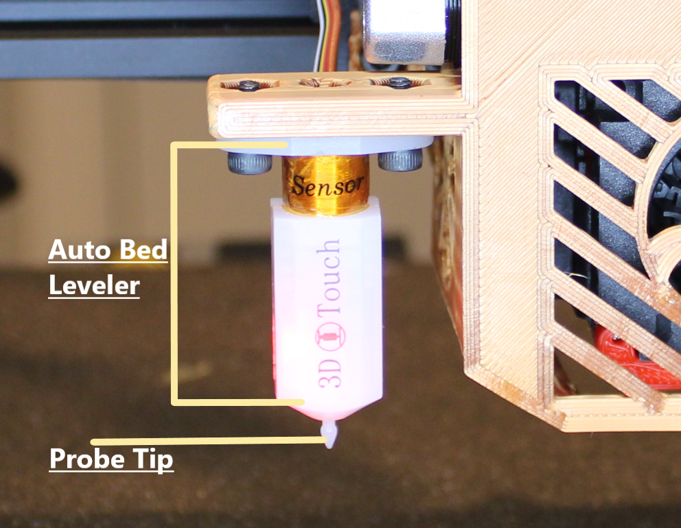
In this article I mention an ABL(auto bed leveler), and a probe. The ABL is the device itself that houses all the components. The Probe is one of the components of the ABL. It’s the arm that deploys and touches (or probes) the bed surface
The attached photo shows a 3D Touch - a clone of the BL Touch - attached to the fan shroud of a Voxelab Aquila S2.
How the ABL Works
In order to understand the importance of the X and Y offsets, let's first look into what an ABL actually does and how it goes about doing it. An ABL works in two phases.
Phase One is measuring the bed and determining the bends and dips of the surface. This is the action you see when the probe is moving up and down from point to point across the bed surface. The ABL extends the probe and lowers the axis until the probe makes contact with the bed. This contact pushes the probe inward, which triggers a sensor within the ABL to activate and record the data.
The number of points, and amount of probes, are all settings determined in the printer’s firmware.
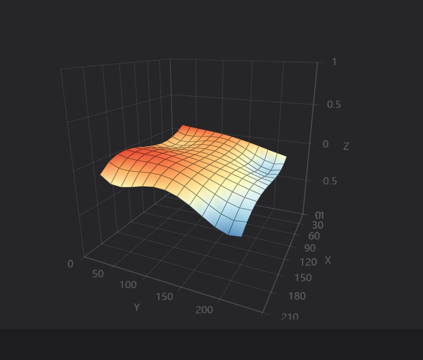
Using those data points, the printer creates a virtual mesh, or map, of the topography of the bed. This procedure is commonly referred to as ‘Creating a Bed Mesh’. This phase is performed either before each print starts, or can be performed outside of a print, saved, and the information can be called upon instantly before a print.
An example of a virtual mesh of a print bed, created from ABL probing data.
Phase Two is moving the Z axis up and down to compensate for the bed's unique bends and dips in an effort to achieve a flat first layer (and subsequent layers based on the fade height - see bottom of page for more details).
This phase happens while the printer is printing
Using the information we gathered in Phase 1 the Z axis moves up and down to match the nozzle to the contours of the bed. This phase may be very hard to notice, as the adjustments in height are usually very small (+/- 0.2mm) and are performed quickly and fluidly. If you want to try to notice if this phase is operating, while the first layer is printing, put your hand on the coupler attached to the z axis. You should be able to feel some small movements and vibrations, that's the ABL doing its job.
The X and Y Offsets
During Phase One the ABL collects data, and then during Phase Two it applies that data by moving the nozzle along the contours of the bed. In order to do this accurately the ABL
needs to know where its probe is in relation to the nozzle.
The nozzle is an ‘anchor point’, it’s a known position, what the ABL doesn't know is where the probe is in relation to this ‘anchor point’. If the ABL doesn’t get the correct probe location (the offset) the probe coordinates will not be in sync with the bed coordinates, and eventually during Phase Two of the ABL’s functions it will be adjusting the nozzle based on the wrong positioning.
The offset values are based on a coordinate system, by default the X and Y offsets are set to X=0, Y=0 or (0,0). At (0,0) the probe thinks it’s directly in line with the nozzle. Because the ABL needs space to deploy this will never be the case, so we need to measure the distance between the probe and the nozzle. If we do not take correct measurements the probe will not have an accurate location of where the nozzle is and all the height adjustments it makes will be along the wrong parts of the bed.
THE ABL DETERMINES IT’S LOCATION ON THE BED BASED ON THE OFFSET OF THE NOZZLE. IF THAT OFFSET ISN’T CORRECT THE ABL WILL BE ADJUSTING THE NOZZLE BASED ON THE WRONG AREAS OF THE BED.
Again this might not be noticeable on some prints, especially if the offset data is only incorrect by a few millimeters. However, over the long term this problem can mar prints and cause issues.
Example
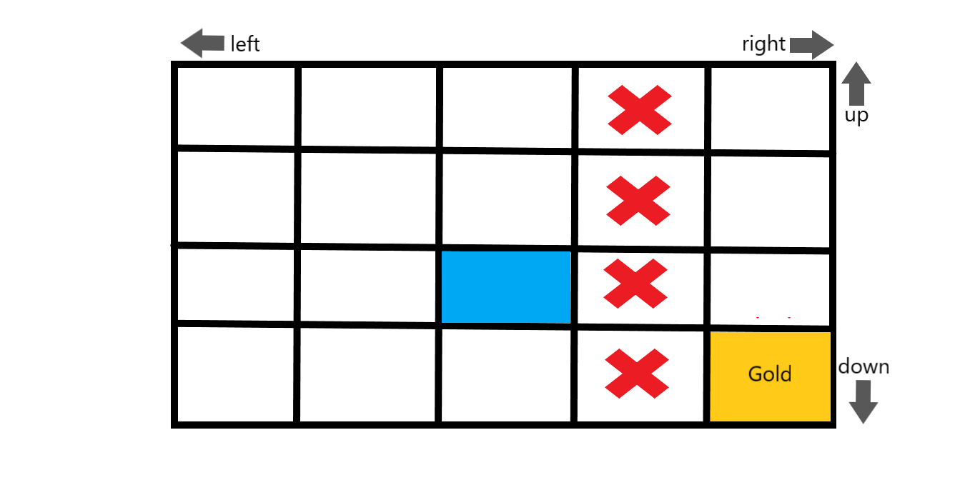
Imagine you're an adventurer in an RPG dungeon. The image to the left is a map of the dungeon where each box represents a room to explore. In this game you need to reach the room with Gold inside without getting hurt. To help guide you is an invisible spirit companion that scouts out all the rooms around you and warns you of possible dangers. You are standing in the Blue center room, your goal is the Gold colored room.
The spirit warns you
“Don’t come into this room, it's a trap!”
Well that doesn’t really help you does it? We need to know where the spirit is in relation to us.
“How far away from me are you?” you ask.
The spirit replies “ I am only one room to your right”.
With that knowledge you can start to determine which room is a trap. But there’s more than one room to your right, the spirit will need to give you more coordinates if you don’t want to be felled by a trap.
“I am one room up!” The spirit bellows.
BINGO! You now can pinpoint the exact room the trap is in based on BOTH the coordinates the spirit gave you! You can now safely navigate the dungeon, grab the gold, and escape without harm(hopefully).
This is a ‘fantastical’ example but it’s attempting to help understand how Offsets can pinpoint location. It’s one thing to know the information about a location, but it’s the offsets that tell us where that location is, so we can use the information properly.
Measuring The Offsets
Even knowing how important these offsets are, actually measuring them can still be a bit tricky. We need to measure along two planes, the X and the Y. We can't simply measure a straight line from nozzle to probe, we need to measure straight out in one direction and then 90 degrees in the other. There's many different ways to do this. I've tried using a ruler, measuring with a set of calipers, drawing dots along my bed surface… the list goes on. The problem with those methods is they can be difficult to get accurate. The best and simplest way I've found to measure these offsets is to use the on board the screen coordinates that your printer provides, and a post it note.
Home the printer and write down the coordinates
On your printer screen there will be the current coordinates for all the axes (X, Y, and Z). After homing the printer, write down the current X and Y coordinates on a sheet of paper, we’ll call these STARTING.
Get a post it note, make a dot, line it up with the bed probe, and stick it to the bed
Grab a post it note (or similar sticky paper- painter’s tape, etc) and using a pen place a dot somewhere on the note. Then stick the post-it to the print bed making sure to line up the dot just underneath the probe tip. You’ll need to be examining the dot and the probe tip from all sides to make sure it is lined up. (also if you’re using a PEI bed you may want to remove it before this process so you don’t get your fingerprints all over it.)
Move your nozzle over to the dot, just as the probe was and record the coordinates
Now using your screen (or web page if using Octoprint of Fluidd) move your nozzle until it is directly over the dot on the post-it note. If you overshoot the dot don’t worry, all that matters is when you end this process the nozzle is lined up with the dot just as the probe tip was. When you’re satisfied you’ve gotten it right, look at the coordinates on your screen and record this new set of X and Y coordinates. We'll call these numbers ENDING
Subtract the STARTING coordinates from the ENDING coordinates
Take your ENDING coordinates and subtract your STARTING coordinates. If you get a negative number that’s fine as the offsets may be negative. For the X coordinate if the probe is to the left of the nozzle(based on the front of the printer) it will be a negative number. For the Y if the probe is in front of the nozzle (based on the front of the printer) it will be a negative number.
You now have accurate offsets for your ABL probe!
HOW DO WE ADD THESE OFFSETS?
Where to input the offsets can vary between printers and even between firmwares. For Marlin based 3d printers (meaning most stock 3d printers) there should be a menu accessible from the screen that will allow you to input them. Usually it’s under Configuration > Advanced > Probe Offsets. If your printer is equipped with Klipper, input the offsets in the printer.cfg file under the [bltouch] section. Make sure on either firmware that you SAVE SETTINGS to make sure these offsets will persist after powering down your printer!
Start in the configuration menu
Then enter advanced settings
find probe offsets
enter your offsets
Where you will input offsets in Klipper
What is Fade Height ?
A lot of people are unsure how long the ABL continues to alter the height of the nozzle along the print bed. Does it only affect the first layer? Does it apply the mesh throughout the entirety of the print? The answer to that is:
The ABL continues to apply and compensate for the mesh data up until it reaches the FADE HEIGHT.
The reason it’s called ‘Fade’ height, is that the printer will gradually start to decrease the influence of the ABL the closer the layer is to the Fade Height value. As the layer height reaches the Fade Height the printer will gradually decrease the effect of the ABL’s influence. Commonly a fade height of 10mm is standard. This means the ABL will be using the mesh data and adjusting the nozzle for 10mm of vertical height. The ABL will gradually decrease the amount of movement the closer it gets to that 10mm height.
