

New to 3D printing? You’ve come to the right place!
If you’re new to 3d printing, getting started can be daunting. Are there any immediate UPGRADES necessary? Are there CALIBRATIONS to perform? The answer to both those questions is YES! Below is a list of equipment UPGRADES and printer CALIBRATIONS I recommend to get you started. Some of the upgrades should be done immediately because the stock equipment is lacking, while other upgrades can wait, giving you time to use your 3d printer and find out its intricacies. Alongside each upgrade I list when and why you should add them. The calibrations should all be done immediately to give you the most consistent possible printing experience. The links below will bring you to a page customized to those individual printers. If your printer is not listed below, continue to the bottom and follow the ‘default’ guide for best practices. If you’re looking for some slicer PRINTING PROFILES I have those, as well as a video to help GET YOU STARTED USING ULTIMAKER CURA.
For the Creality Ender 3 series click here!
For the Creality Ender 5 series click here!
For the Eryone ER20 series click here!
If your printer is not listed above follow the section below as a ‘default’ guideline. you can always drop me a line and ask for a webpage dedicated to your printer.
Upgrade Overview

Immediate Upgrades:
Cold end extruder - BMG Dual gear extruder clone : https://amzn.to/3f7K8vQ official : https://amzn.to/3MXZZd7
Bowden tube - Capricorn Bowden Tubing : https://amzn.to/3W0MwoP
Bed springs - Yellow Stiff Bed Springs : https://amzn.to/3SwIUrT
Moderate upgrades:
Firmware upgrade - 3d printer dependent
All metal hot end/bi metal heatbreak - Gulf Coast Robotics All Metal Hot end : https://amzn.to/3gEkPCh
Quality of life upgrades:
PEI bed sheet - Hictop textured PEI bed sheet and bed magnet : https://amzn.to/3TOP0ER
AutoBedLevel probe - BL Touch official : https://amzn.to/3VXGfdB clone : https://amzn.to/3slxZ9T
Calipers - digital : https://amzn.to/3gwllC5
Nozzles (assortment) - MK8 : https://amzn.to/3gEmuaY
Fans(noise) - parts cooling fan 24v : https://amzn.to/3CXjNsq hot end/mainboard fan 24v : https://amzn.to/3TuQncn
Immediate Upgrades
-Default Guide-
Cold End Extruder
The cold end extruder (along with the extruder stepper motor) drives filament forward towards your nozzle. The stock extruder for most 3d printers is made of cheap/weak plastic. Over time the extruder will adopt hairline cracks that are not visible to the naked eye. These cracks weaken the extruder causing it to lose tension and not be able to push out the correct amount of filament. There are 3 main upgrades you can choose from:

If your extruder is made of plastic and looks similar to this one it’s recommended to replace it. This is the stock Voxelab Aquila extruder, but the same comes stock on the Ender 3 Pro.
Dual Gear BMG clone - This extruder is not only a replacement but a strict upgrade. This offers dual geared movement(opposed to the stock single gear) which offers more accurate extrusion. The enclosed nature of this extruder also allows the ability to easily(nothing in 3d printing is easy lol) print with flexible filaments like TPU. The original model is the BONDTECH BMG. It’s an expensive option but this is the company that is doing the work to make the advancements in technology. The various BMG ‘clones’ are great. They are cheaper and copy the original in almost every aspect. The quality of these is not as high as the original but more often than not you will receive a fine product. Out of the options I discuss, this is the choice I recommend!
Difficulty: 1-5 = 3 fairly simple removal and install. New e-steps(see calibrations) will have to be calculated afterwards and they will be higher than normal - around 400-420.

This is a clear BMG clone style extruder. It is enclosed and made of injection molded plastic.

Dual Gear All Metal - Just like the BMG clone this extruder offers dual geared movement. That means this is an upgrade as well as a replacement. The issue with this extruder is the second gear that sits inside the tension arm. If there is not a spacer on that gear then it will eventually grind into the arm throwing metal filings in the process. If you cannot confirm the gear has a spacer with it then DO NOT BUY this extruder. I have linked extruders that do include the spacer, but double check before buying as sometimes companies are known to change the products in their listings. I was able to print flexible filaments, like TPU, with this extruder.
Difficulty: 1-5 = 3 fairly simple removal and install. New e-steps(see calibrations) will have to be calculated afterwards and they will be higher than normal - around 130-150.

All metal dual gear extruder. The linked product shows the necessary bushing within the tension arm to keep the extruder from grinding itself away.

SIngle Gear All Metal - This style of extruder is an exact copy of the stock extruder only it’s been cast in metal, so it will not crack and lose tension. This is a fine replacement for the stock extruder, however it’s not an upgrade, as it still uses a single gear.
Difficulty: 1-5 = 3 fairly simple removal and install. New e-steps(see calibrations) will have to be calculated afterwards and they should be around the normal range - 93 - 98.

Shown here is a red all metal single geared extruder. These can also often be found in sliver.

Here’s my video that goes over a few of these options and the removal and installation process.
Bowden Tube (PTFE tube)
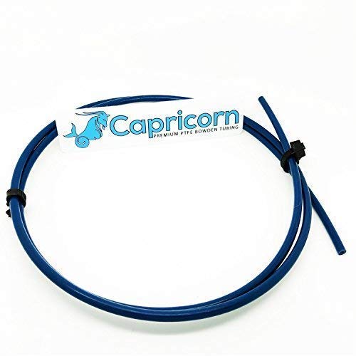
Referred to by two names - bowden tube(mechanical name) and PTFE tube(material name - PolyTetraFluoroEthylene), this is the tube that directs and constricts the filament path between the cold end extruder and the hot end. On some models the bowden tube reaches all the way down to the nozzle (the list includes but is not limited to - Aquila, Ender 3, Ender 5, Eryone ER20, Jayo S8). The bowden tube is made up of teflon and if it reaches high temperatures (~240c and above) it can off-gas harmful toxins. If you want to print higher temperature materials this a must replace for any printer where the tube is touching the nozzle. The stock tube has a larger diameter path and is of unknown origin, a direct upgrade is a Capricorn Bowden tube. This tube has a narrower filament path, allows the filament to be fed easily, and can withstand higher printing temperatures (up to 260c). This is a slam dunk upgrade as this is the best company and the installation is simple.
Difficulty: 1-5 = 1.5 simple removal and install. You may need to heat the hot end to get your stock bowden tube removed.

The red arrows are pointing out the blue capricorn bowden tube that extends from the cold end extruder to the hot end.
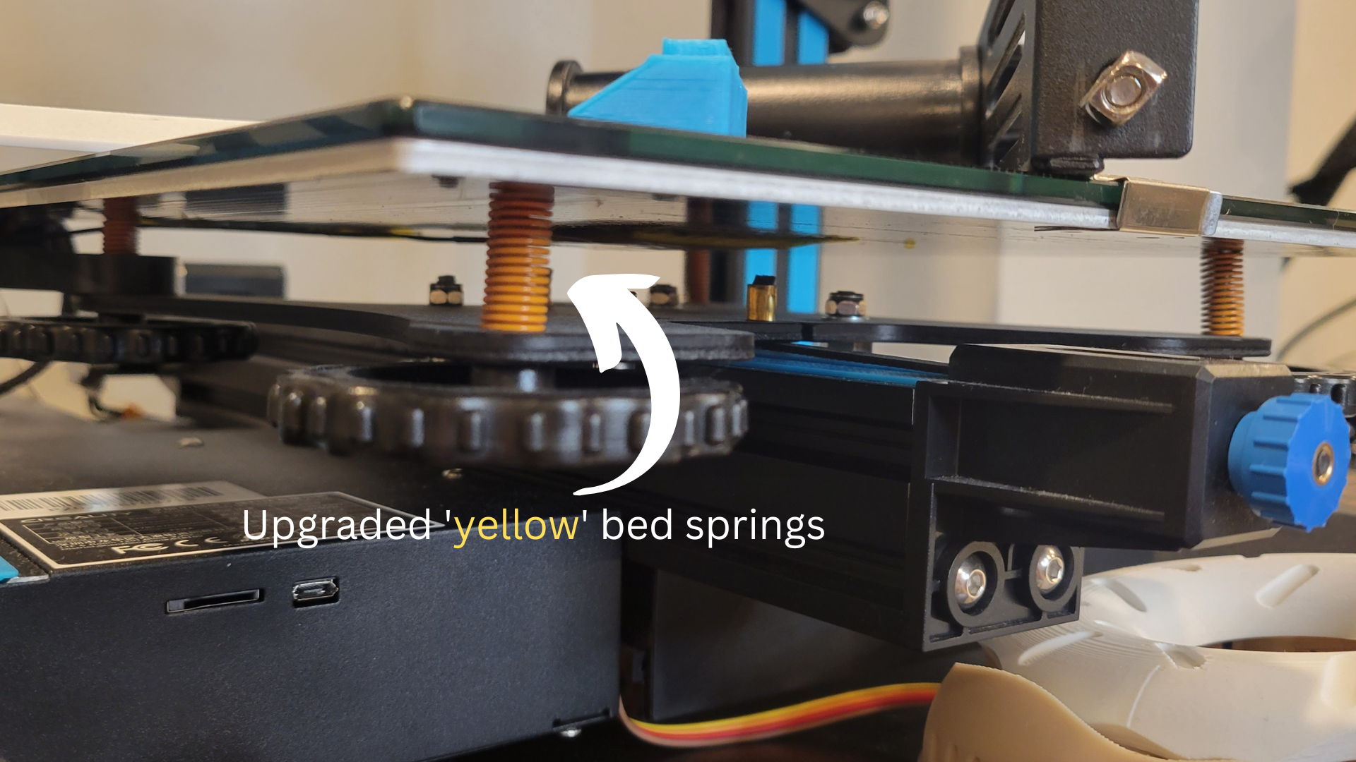
Bed Springs(yellow)
If you don’t know this already the end all be all of printer calibrations is leveling your print bed. The items that keep your bed level are the springs. Stock bed springs offer moderate tension and can distort over time, meaning you’ll be re-leveling your bed more often than you’d want. Upgraded bed springs, usually yellow in color, off a stiffer spring which should keep your bed at a more consistent level over a longer period of time = leveling your bed less.
Difficulty: 1-5 = 2 replacement is not hard but care should be taken while doing so. Releasing any one adjustment knob fully can warp your bed, so take your time and slowly loosen each knob until you can remove the, and replace the springs. I go over the loosening procedure in my BED LEVELING video (see Calibrations).

CALIBRATIONS
This section will go over each fundamental calibration, how it should be performed, when it should be performed, and how often to maintain them. Any 3d printer can be defective out of the box, there are always going to be bad units. The vast majority of printers however are capable, and when calibrated effectively will far out kick their coverage. You will get out what you put in, so please, if you want consistent quality prints, take your time with these calibrations. Try to understand their ‘core’ principles. Don’t expect results to be immediate, certain calibrations take time to implement properly, you get better each time. Reading and comprehending is one step to get there, but getting your hands on your printer and performing these is the only real way to get a ‘feel’ for how they work. Don’t get discouraged, take your time, and remember proper fundamentals -while boring- are the building blocks of accurate consistent machines.
For a more robust set of directions (with pictures) each section also has it’s own accompanying page. The link will be next to the title
E-Steps
E-steps, also known as extrusions steps, are the rotations necessary for the extruder stepper motor to move a set amount of material. This calibration is one we are performing for the stepper motor itself. The X,Y, and Z axes stepper motors are all already calibrated and their e-steps have been set. The extruder motor, however, is one we need to calibrate for ourselves. This calibration is to make sure:
WHEN WE ASK THE PRINTER TO EXTRUDE X AMOUNT OF FILAMENT, IT EXTRUDES X AMOUNT OF FILAMENT, NO MORE, NO LESS.
The general principle behind this calibration is that you will tell the extruder to move 100mm of filament. You then measure the extruded amount hoping it equals what was asked for. When it isn’t we plug certain values into a formula, which tells us how to adjust our e-steps. For this calibration we DO NOT want to extrude filament through the nozzle. We want the filament to be measured directly from the cold end extruder. We are calibrating the extruder motor, if we send filament through the nozzle we introduce unwanted variables (i.e bowden tube, material type, nozzle, temp, etc). We calibrate the amount of filament that extrudes from the nozzle in a separate step. This is a mechanical calibration of only the stepper motor. This way if we are to make changes to any other equipment - nozzle, bowden tube, filament type/brand, hot end - we do not have to re-calculate our e-steps.
The process for a Bowden-style 3d printer and a Direct-extrusion style 3d printer are similar, but differ enough to warrant their own sections below.
Bowden style 3d printer

Direct-extrusion style 3d printer (direct drive)
-
Bowden style printers - This calibration is easily performed with bowden printers(where the cold end and hot end are separated and connected by the use of a Bowden Tube).
Tools needed: flush cutters , calipers/ruler
Before beginning you need to get the current e-step value from your 3d printer. Write this number down somewhere.
Each printer is slightly different but it’s usually located under a similar file path. Using the menu navigate to:
Configuration > Advanced > Steps/mm > E-steps
The general stock e-step value is 93.0
Remove filament from your 3d printer if any is loaded
Heat your hot end to temperature, when the filament has softened, remove it from the machine. Keep your nozzle at 185c or slightly above for the remaining steps.
Disconnect the bowden tube from the cold end extruder
Generally this is done by removing the collet(usually blue), which looks like a small semi circular pin, that is holding the plunger attached to the coupler where the bowden tube is sitting.
Once removed, depress the plunger of the coupler, keep it depressed(the movement is slight, maybe 1-2mm), and remove the bowden tube by pushing inwards and then retracting outward.
It’s possible the Bowden tube can become stuck within the coupler. If that is the case you may need to remove the entire coupler by using a small wrench (supplied with printer) to unscrew the coupler.
Manually depress the tension arm of the extruder and pass filament through until it comes out of the now open end of the extruder.
With a pair of flush cutters, cut the filament flush with the end of the extruder opening.
Using your menu(or home screen if using a web-based application like Octoprint) extrude 100mm of filament.
Most 3d printers have a safety feature that won’t allow filament to be extruded while the nozzle is cold i.e until a minimum temperature is reached. If that’s the case, bring the nozzle up to just above minimum temperature (usually 185-190c) to be able to extrude filament.
After the printer is finished extruding use the flush cutters, and again as you previously did, cut the end of the filament flush with the extruder.
You should now, theoretically, have a segment of 100mm of filament. Using a pair of calipers or a ruler, measure the distance of the extruded piece of filament.
This measurement is done in millimeters and be as accurate as you can to the nearest millimeter.
If the measured piece of filament is 100mm then you’re done! However it’s likely not, so we use a formula to determine what the correct number of e-steps should be to move the correct amount of filament. The formula is as follows:
Amount of filament asked to extrude / Amount of filament extruded * current e-step value = new e-step value
For example if the amount of filament asked to extrude was 100, the amount that was actually extruded was 98, and your current e-step value is 93.0 than the formula would look like this:
100 / 98 * 93 = new e-step value
1.020 * 93 = 94.8979
Round up to the nearest tenth and we get a new e-step value of 94.9
Insert the new e-step value into your 3d printer, it will be the same screen where you got the original e-step value from.
Configuration > Advanced > Steps/mm > E-steps . Then change the number to the new value and back out
Remember to Save Settings so the value will persist after powering off. Save Settings should be found under the Configuration menu.
Perform steps 5-9 again
If you have extruded the correct amount of material you are all finished! If not, just use the formula again and continue making adjustments to the e-steps until you have extruded 100mm
Remember if you need to continue making adjustments the ‘current e-step value’ will be different with each subsequent test. Do not use the original value.
When to perform - before doing your first print, you should calculate this! This is the baseline for many other extrusion based parameters, and the key to diagnosing print quality issues. This will only need to be done once, and updated when a new cold end extruder or extruder stepper motor are installed (or converted if going to different firmware i.e. Klipper).
Relates to: flow(extrusion multiplier)
-
Direct Extruder printers - When calibrating the e-steps for a direct style printer the method is mainly the same, we will extrude filament, measure it, and then apply a formula, however due to the physical nature of direct extrusion being able to perform these test can be harder. It’s going to require us to remove the nozzle, and make some feature changes using a gcode file.
Before beginning we need to get the current e-step value from your 3d printer. Write this number down somewhere.
Each printer is slightly different but it’s usually located under a similar file path. Using the menu navigate to:
Configuration > Advanced > Steps/mm > E-steps
The standard stock e-step number is 93.0
Remove filament from your 3d printer if any is loaded
Heat your hot end to temperature, when the filament has softened, remove it from the machine.
Remove the nozzle from your hot end.
Most nozzles should be heat tightened, and thus, need to be heated to be removed. Start by heating your nozzle up to 240c
In the meantime get all the tools you’ll need for the removal. I usually use a socket wrench and a large crescent wrench that holds the heat block in place.
Once the nozzle reaches operating temperature power down the machine. We never want to touch the hot end while it is powered on. We can accidentally short out the thermistor, heating cartridge, or even the mainboard!
While the nozzle is still hot, remove it.
Using your Crescent wrench brace the heating block, making sure not to clamp any wires going into the hot end.
With the socket wrench begin to remove the nozzle
KEEP IN MIND THE NOZZLE AND HOT END ARE AROUND 240c. Handle everything carefully and take caution to not burn yourself. It is recommended to wear thermal resistant gloves while doing this. When the nozzle is removed from the heating block it will be a hot ember within your socket wrench so make sure to have a place to rest it.
With the nozzle removed, wait for the heating block to cool. We want to pass filament through the heating block while it’s cool, so the filament doesn’t melt.
Once the heating block is cooled manually depress the tension arm on the extruder and pass filament through to the now open end of the heating block.
With a pair of flush cutters, cut the filament flush with the end of the heat block opening.
Using your menu extrude 100mm of filament (or home screen if using a web-based application like Octoprint, etc).
Most 3d printers have a safety feature that won’t allow filament to be extruded while the nozzle is cold i.e until a minimum temperature is reached. Which makes this step difficult for direct extrusions machines.
Do not want to pass filament through the heating block while it is hot.
You’ll need to run a line of gcode to temporarily disable this feature. If you have access to the terminal line of your printer (through Octoprint) you can enter and send this line []
If not you will have to download this gcode file, load it onto an sd card, insert it into the printer, and then ‘Print’ the file like you would any 3d printing file. This sends the gcode to the printer and lets us bypass the minimum temperature requirement for extrusion.
After the printer is finished extruding use the flush cutters again, and as you previously did, cut the end of the filament flush with the heating block.
You should now have a segment of 100mm of filament. Using a pair of calipers or a ruler, measure the distance of the extruded piece of filament.
This measurement is done in millimeters and be as accurate as you can to the nearest millimeter.
If the measured piece of filament is 100mm then you’re done! However it’s likely not, so we use a formula to determine what the correct number of e-steps should be to move the correct amount of filament. The formula is as follows:
Amount of filament asked to extrude / Amount of filament extruded * current e-step value = new e-step value
For example if you asked to extrude 100, and your printer extruded 98, and your current e-step value is 93.0 than the formula would look like this:
100 / 98 * 93 = new e-step value
1.020 * 93 = 94.8979
Round up to the nearest tenth and we get a new e-step value of 94.9
Insert the new e-step value into your 3d printer, it will be the same screen where you got the original e-step value from.
Configuration > Advanced > Steps/mm > E-steps . Then change the number to the new value and back out
Remember to Save Settings so the value will persist after powering off. Save Settings should be found under the Configuration menu.
Perform steps 5-9 again
If you have extruded the correct amount of material you are all finished! If not, use the formula again and continue making adjustments to the e-steps until you have extruded 100mm
Remember if you need to continue making adjustments the ‘current e-step value’ will be different with each subsequent test. Do not use the original value.
Re-install your nozzle.
Power down the 3d printer
Manually depress the tension arm of the extruder and remove the filament
Hand-screw and tighten the nozzle onto the heating block
Using the socket wrench and crescent wrench snug the nozzle up carefully
Heat Tighten the nozzle
Power the 3d printer on and bring the nozzle up to 240c(higher if you have an all metal hot end)
When the printer reaches operating temperature, power it down. We never want to touch the heating block while the printer has power.
KEEP IN MIND THE NOZZLE AND HOT END ARE AROUND 240c. Handle everything carefully and take caution to not burn yourself. It is recommended to wear thermal resistant gloves while doing this.
Using the socket wrench and crescent wrench tighten up the nozzle. Do not overtighten the nozzle or apply a great deal of strength. That could cause the nozzle to break off within the heating block.
The purpose of heat tightening is - as metal expands, with heat, it can cause the threads to expand and loosen. Heat tightening the nozzle snugs the nozzle up while at temperature making it the tightest possible connection. This way during a high temperature 3d print there’s no space for filament to ooze within the threads which can lead to a clog.
When to perform - before doing your first print, you should calculate this! This is the baseline for many other extrusion based parameters, and the key to diagnosing print quality issues. This will only need to be done once, and updated when a new cold end extruder or extruder stepper motor are installed (or converted if going to different firmware i.e. Klipper).
Relates to: flow(extrusion multiplier)
Bed Leveling (Tramming)
(link to the article page)
This is the end-all be-all calibration for most all 3d printers, and it’s paramount that you understand what we are trying to accomplish with it. That is, to get the plane of the nozzle and the plane of the bed parallel to each other, and the way we do that, in simple terms is TO GET THE NOZZLE THE SAME DISTANCE AWAY FROM THE BED AT MULTIPLE POINTS OF THE PRINT BED. The term ‘leveling’ the print bed is a bit of a misnomer. If you were leveling the bed you could take a ‘bubble level’ from a hardware store, lay it across the print bed and start to make adjustments. That would be leveling it by gravity and that’s not what you are doing. What you are trying to do is get the distance the nozzle is from our bed equal across all areas of the bed, and this is more correctly called ‘tramming’. However misleading the term ‘leveling’ is, it is now common vernacular so I will be using it.
Tools needed: A feeler gauge -something to put between the bed and the nozzle to judge distance- I use a post-it note. The actual thickness of the gauge does not matter. The thinner it is the easier the process should be but the measured thickness is inconsequential (I could use a brick if I wanted to). We only need the feeler gauge to be of uniform thickness. We are just using this to line up the plane of the nozzle and the bed. GETTING THE DISTANCE THE NOZZLE IS FROM THE BED WHILE PRINTING IS DONE THROUGH Z-OFFSET ADJUSTMENT AND IT IS COVERED FURTHER DOWN IN THIS GUIDE. The distance the nozzle is during this step doesn’t matter, only so long as it is uniform at all points!
This calibration can be performed on a powered down or powered on printer, I prefer for it to be powered down. In order to make adjustments to the bed we will be using the adjustment knobs. They are located under the bed at all four corners.
As you tighten the knobs the bed pulls downward and away from the nozzle INCREASING the gap between bed and nozzle (counterclockwise if looking down at the knobs).
When you loosen the knobs the bed rises up towards the nozzle DECREASING the gap between bed and nozzle (clockwise looking down at the knobs).
To make this easier to follow I will label each adjustment screw with a number, the orientation corresponds to if you were standing in front of the 3d printer facing it, using your left and your right as identifiers (i.e if you were standing looking at a STOP sign the ‘S’ is on the left and the ‘P’ is on the right).
Number 1 is the Front Left adjustment knob
Number 2 is the Front Right adjustment knob
Number 3 is the Back Right adjustment knob
Number 4 is the Back Left adjustment knob
Begin the process by getting your nozzle over adjustment knob 1 and as close to the bed as possible without it touching.
There are several ways to do this. On a powered down printer, I manually move the printhead over the adjustment knob. Then I turn the coupler on the Lead screw which lowers the nozzle to the bed.
As the nozzle gets closer to the bed, place your feeler gauge of choice between the nozzle and the bed.
Begin moving the feeler back and forth.
While the nozzle and bed are not compressed you are able to freely move the feeler. As the nozzle gets closer to the bed the movement of the feeler gauge decreases, and you can begin to feel resistance. When the nozzle is close enough it traps the gauge and it can no longer move.
When you get the nozzle close enough to the feeler to feel some resistance begin using the Adjustment Knob to make smaller changes.
While performing this calibration you want the nozzle close enough to the bed that you can still move the feeler gauge freely, but also compressed enough to feel tension(resistance). Use that resistance to GET THE SAME TENSION AT ALL POINTS, that's the goal here. Equal tension at all points means the nozzle is equidistant at all points meaning the planes are lined up.
The amount of resistance is completely up to you. However much you need to feel comfortable enough to uniformly apply it to each adjustment knob as you proceed.
If the nozzle is too close to the bed, turn the Adjustment Knob counter clockwise to increase the nozzle gap.
If the nozzle is too far from the bed, turn the Adjustment Knob clockwise to decrease the nozzle gap.
When you get adequate resistance at Adjustment Knob 1 manually move the printhead over Adjustment Knob 2.
At this point you will no longer be moving the nozzle up and down using the lead screw coupler, the adjustments going forward (even the subsequent adjustments to knob1) will be performed using only the adjustment knobs.
At Adjustment Knob 2 place your feeler gauge between the nozzle and the bed and make adjustments to Adjustment Knob 2 so that you have the same resistance as you did on Adjustment Knob 1
If the feeler gauge cannot go under the nozzle at first, tighten the screw (by turning it counter-clockwise) creating a gap to get the feeler gauge underneath.
The adjustment is dynamic, if you get too close or too far that's fine, all that matters is the distance when finished.
When the resistance on the feeler gauge at Adjustment Knob 2 is the same as it was at Adjustment Knob 1, manually move the printhead overAdjustment Knob 3.
Perform the same process you did in STEP #6, making adjustments until the resistance on the feeler gauge is the same as the previous two Adjustment Knobs.
When the resistance of Adjustment Knob 3 is the same as it was for Adjustment Knob 1 and 2, manually move the printhead to Adjustment Knob 4.
Perform the same process you did in STEP #6, making adjustments until the resistance on the feeler gauge is the same as the previous three Adjustment Knobs.
When the resistance on the feeler at Adjustment Knob 4 is the same as it was for all the previous Adjustment Knobs, manually move the printhead over Adjustment Knob 1.
Start the process over, making Adjustments to each knob in the same pattern as before.
Remember you are no longer making any changes using the lead screw coupler, only at the Adjustment Knobs.
Be careful to bring the nozzle over the same location you did the first time, being ‘around’ or ‘near’ the location could give you skewed results.
It’s normal for all the resistances to be off after going through the first round of adjustments.
As you make adjustments to an Adjustment Knob it affects the Adjustment Knob diagonally from it (1 and 3, 2 and 4).
On your second round of adjustments you will likely still need to make some gross adjustments, DO NOT WORRY. With each subsequent pass you should need to make smaller and smaller adjustments, until, ultimately, you will no longer have to make any adjustments at all.
Continue going through this process until the resistance at each knob is uniform
DO NOT RUSH THIS. this is the hallmark calibration, if you’re going to spend extra time anywhere this is the spot. Be patient.
Why do we only check the bed at the four corners?
We only really have agency over the areas that are directly above the adjustment knobs, so that's where we tram the beds. The hope is that your bed is flat enough that when it is level at these four points it should be adequate enough to carry through to the entire bed.
After bed leveling I try and put my feeler gauge under my nozzle at the center of the bed but it won’t fit/there’s too much gap!
Again we only have the ability to make precise adjustments at where the adjustment knobs are located. Having the fifth point (bed center) incongruous to the four corners is not abnormal and it is a product of a warped bed. THAT DOES NOT MEAN YOU CANNOT PRINT AND GET QUALITY PRINTS. It just means you have to be extra diligent with bed leveling and getting the four corners as accurate as you can. Most all 3d printer beds are warped to some degree.
I want to get an auto bed leveling device like a BL Touch so I don’t have to level the bed again!
Another misnomer in 3d printing is the term ‘auto bed leveling device’. BL touches and devices like it DO NOT LEVEL YOUR BED, I’ll repeat it for the people in the back ‘auto bed level devices’ DO NOT LEVEL YOUR BED. You will still need to level your bed! (albeit it should be far far fewer times). What auto bed level devices do is take height measurements at a set number of ‘probe points’ on your print bed. Then it uses that height data to extrapolate the actual curves and contours of your bed. The printer uses this data to create a virtual topography (known as a mesh) of your bed and uses that mesh to ADJUST THE HEIGHT OF THE NOZZLE while it prints the first layers of your print. This helps print flat first layers, and moreover, helps print on a warped bed
When to perform: Often. Before your first print. If the 3d printer is moved locations. If there is noticeable loss of adhesion to prints. When first layers begin to look uneven over the breadth of the bed. If you change any of the following: nozzle, bed surface, hot end assembly, bed screws.
Relates to: z-offset
