Automatically perform input shaping on your 3d printer with a KUSBA (or other) accelerometer
3d Printers are getting faster, more precise, and more complicated. Calibrations you may have avoided years ago are now a necessary step in order to produce high quality prints while still maintaining higher than average print speeds. Input shaping is one such calibration. A topic that is somewhat veiled in mystery (and misinformation) this article is hoping to draw back the curtain on Input shaping, explaining how it works and just how easy it is to implement. If you want to explore more on this topic, or just prefer an audio/visual experience please watch my accompanying video on Input Shaping
This article will cover:
What is Input Shaping in 3d printing?
How do we perform the Input shaping Calibration?
Using the Input Shaping data for better 3d prints
Configuration and setup of the KUSBA accelerometer
What is Input Shaping?
Input shaping is an open loop control system we implement to ‘counter’ the vibrations of our 3d printer which are at a resonant
frequency. Well what does that all mean? Simply put, input shaping is an algorithm, or an equation, that when given the onboard
vibration values, plots an (electrical) signal contrary to that signal. The original signal, the signal which would normally be sent to
the stepper motor, then gets convolved (fancy mathematical term for combined) with the input shaper signal to produce a new
command signal. It's this new signal that is sent to the stepper motor that reduces vibrations. Input Shaping is an open loop system
which means it will only be given data at the beginning of operation (start of a print), and then it will implement that data
continuously. The input shaping system does not take feedback and produce a new signal. That means we will never perform input
shaping calibration while printing. The calibration is performed outside of printing, the data is interpreted, and then the results are
implemented while we print.
What exactly is an input shaper, and why do we have 5 of them?
An input shaper, put simply, is an algorithm. An input shaper is not a physical quantity, it's not a machine, it's an equation. It uses
vibration data as a variable in an equation, and outputs a final result. That result will be a 'new signal' for the stepper motor to use,
and it will be 'shaped' based on the input shaper used. The difference between each input shaper is the equation they use. Certain
shapers are similar in nature but not identical. The five input shapers that Klipper uses are:
ZV and MZV
Zero Vibration input shapers. Best used for cancelling out vibrations over a narrow range of resonant frequencies
EI , 2hump EI, and 3hump EI
Extra Insensitive input shapers. Best used for cancelling out vibrations over a wider range of frequencies
For example the extra insensitive (ei) shapers have a similar equation, but the more 'humps' you add, the more you add to the
equation (ei, 2hump_ei, 3hump_ei, etc). This differences between input shapers, especially similar ones, make them better at
opposing different types of vibrations.
Ei equation:
u(t) = ∑_{n=0}^{N-1} A_n e^{-\lambda_n t} δ(t - n T)
2hump ei:
u(t) = ∑_{n=0}^{N-1} A_n e^{-\lambda_n t} δ(t - n T) + ∑_{n=0}^{N-1} B_n e^{-\mu_n t} δ(t - n T)
Can you see the difference? 2hump ei applies the same equation twice, which adds that second 'hump'. Can you take a guess what the equation for 3hump ei is?
3hump ei:
u(t) = ∑_{n=0}^{N-1} A_n e^{-\lambda_n t} δ(t - n T) + ∑_{n=0}^{N-1} B_n e^{-\mu_n t} δ(t - n T) + ∑_{n=0}^{N-1} C_n e^{-\nu_n t} δ(t - n T)
How does the testing work?
The testing discussed in this article (graphs, procedures, etc) focuses on calibration with an accelerometer. An accelerometer is a tool that measures acceleration, which for our application, usually looks like a small circuit board (ADXL, KUSBA, etc)
Manual input shaping, without the use of an accelerometer, is also available but the procedure is much different than what will be covered here. If you are interested in manual calibration (using a printed model for testing) check out Klipper’s official documentation.
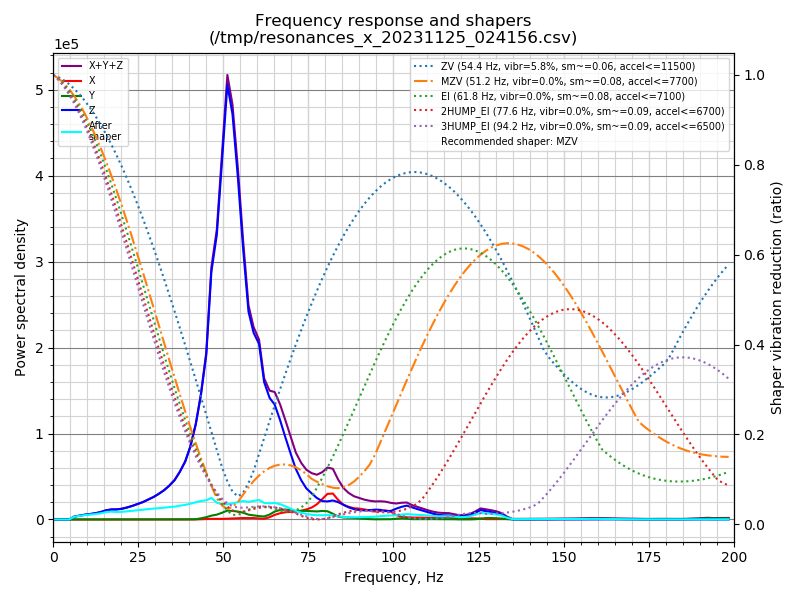
The input shaping test produces vibrations along a single axis of the 3d printer. The stock test begins vibrating at 5 hertz(Hz) continuing all the way up to 133Hz. The attached accelerometer measures the impact(aka strength) that those vibrations have on the axis during the test. Afterwards the vibration data obtained will be visualized on a graph, and will appear as a large spike(or spikes) at certain hertz
An input shaping graph produced after testing that shows the recorded spike in vibration(blue) and the five separate input shapers being visualized behind it. This graph is explained in further detail at the bottom of this article.
Also plotted on this graph are 5 different input shapers (zv, MZV, ei 2humpEI, 3humpEI), and they appear as waves in a contrary direction of the spikes of vibration. It's this graph that we use to interpret which input shaper is the best choice for our 3d printer.
USB Accelerometer Setup:
Prepare Klipper
If this is the first time you're attempting to run automatic input shaping (with the use of an accelerometer) on this Klipper host device (ie. raspberry pi, Inovato Quadra, PC), then you’ll first need to make some updates to the device.
*If you have already set up some automatic input shaping, using a triangle labs USB accelerometer for instance, and are just looking to setup up the KUSBA device, then you can skip this first part.
Before we begin working with automatic input shaping we first need to set up the Klipper host device so it can perform the necessary ‘input shaping’ routines. To this end we need to install some dependencies onto the Klipper host device. To do this we first need to SSH into our Klipper host device.
SSH is a way to wirelessly communicate with the Klipper host device. The above photo shows one available service for SSH, PuTTY.
While at the terminal line run the following commands which will download and install the necessary components for the accelerometer and input shaping routines. This will likely take a few minutes. (These commands can all be executed at the same time as a single block)
~/klippy-env/bin/pip install -v numpy
sudo apt update
sudo apt install python3-numpy matplotlib libatlas-base-dev
That’s it for configuring the Klipper host device, very simple right? Don’t exit out the terminal line just yet we are still going to be working on it.
USB Accelerometer Setup:
Find the KUSBA v2 beginning address
*if you skipped the above steps you first need to SSH into your Klipper host device.
In order to communicate with the KUSBA we need to find its device address while it’s plugged in. The following line will need to run twice. Once without the KUSBA plugged in (now), and then once after it has been plugged into the host device.
*The device will usually(but not always) be named SDA1 so be on the lookout for the absence of that address
At the terminal line, while the KUSBA is not plugged in, execute the following command:
ls /dev
Note the return results (there should be many). You can take a screenshot if you’re worried but because we aren’t closing this terminal window, you should be able to view them again by scrolling up in the terminal
Now plug the KUSBA into the Klipper host device while holding down the button on the KUSBA (which places it in a flash state).
Run the same line again and check the output:
ls /dev
This time check for any new device names. The KUSBA will likely be named SDA1 but double check all the entries and find the address that wasn't there when you ran this line while the KUSBA was unplugged. When you find the address make a note of it.
For my example I will be using SDA1
USB Accelerometer Setup:
Create the KUSBA v2 firmware image
We now need to create a firmware image to flash Klipper onto the KUSBA device. If you have flashed Klipper in the past this will seem familiar to you. For past tutorials I have created images using KIAUH, which is a very helpful tool while beginning the Klipper installation. Because we are only flashing this one device I will be using the more straightforward method of using terminal line commands to create the image.
*Do not close the SSH terminal until noted within this guide. If you do, don't worry you won’t damage anything, but you will be working within different folders for this process, and in order to make sure you are in the correct folder it’s easier (and quicker) to keep the same terminal open.
These operations will be executed through the terminal line to:
navigate to the Klipper directory(folder)
clean up any previous Klipper firmware images
open the firmware image creator and setup up the firmware
build the firmware
flash the built firmware onto the device
From the terminal line start by moving to the Klipper directory
cd klipper
Then clean any previous build files
make clean
Now enter the firmware image creator menu
make menu config
Once inside you will need to set the image up exactly like this, by selecting the correct settings:
Micro-controller Architecture: Raspberry Pi RP2040
Communication inferface: USB
*keep in mind this was the correct image for the device that I purchased, KUSBA v2. These products are constantly evolving and changing. If you are having issues flashing your device, double check the chip that came attached to your KUSBA and go to the official github for guidance if there are any changes. [https://github.com/xbst/KUSBA]
In order to build this firmware we need to select Quit, and then Save the settings. Type the letter Q[quit] to be given the option to compile the firmware and save the current settings. Choose to save the current settings and you will be exited back to the terminal line.
Now the firmware needs to be built in order to flash it directly onto the KUSBA. Run the following line:
make

Is the information here, or on my Youtube, helpful? Want to give back?
JOIN MY PATREON NOW
USB Accelerometer Setup:
Flashing the KUSBA v2
The firmware has been created and is waiting to be delivered to the device. You now need to mount, flash, and then unmount the KUSBA. The first command requires you to enter the address that you recorded when the KUSBA was plugged into the host device (a few steps back).
For my example I will be using SDA1 but please make sure you are mounting the correct address. If you are mounting a different address replace all the references to ‘sda1’ in my examples to the address you are using.
(note: in the following lines there is always a space before the command ‘/mnt’)
(note: you can run all these lines simultaneously)
sudo mount /dev/sda1 /mnt
sudo cp out/klipper.uf2 /mnt
sudo umount /mnt
Hopefully you have encountered no errors, which means the flash was successful. If you are experiencing issues at this point, re-read all the above steps and make sure you didn’t miss any.
(are you using the correct serial address? Was the firmware image set up properly? Were there any spelling errors/added spaces within any of the commands you executed?)
For the remaining step we need to exit the Klipper directory:
cd~
At this point I would unplug the KUSBA device from your Klipper host device. Then plug the KUSBA back into the host device, but this time DO NOT hold down the button on the device.
USB Accelerometer Setup:
Configure KUSBA v2 for Klipper
At this point Klipper has been installed onto the KUSBA, and just like you did with your printer you need to create a configuration file. This file will tell Klipper important information about how we want to use the device, as well as telling Klipper what device this is, using a serial address for identification. (This serial address is a different address than the address used above: ‘sda1’.)
If you haven’t moved back to the home directory(folder), do that now. [cd~]
At the top of this page [or maybe right here too] I have provided a KUSBA configuration file for you to download and use. Download that file now.
The official file from KUSBA has changed a few times as each revision of the KUSBA has been released. If this configuration file is not working for you go to the official KUSBA github and see if there are any updates or new releases.
While at the terminal line, With the KUSBA plugged in, run the following line.
ls /dev/serial/by-id/*
There should be a minimum of two addresses returned. One will be your printer, the other the KUSBA. If you can’t distinguish the two apart you can either unplug the KUSBA and run this line again, or go into your printer.cfg and see what your printer is using as an address (it will be under the [mcu] section).
Keep the terminal window open and navigate to your Front End.
I will be using Fluidd for this demonstration but Mainsail is similar enough where you can still follow along
Find the Configuration tab and enter it. The panel on the left side of the Configuration page are all the files that Klipper is using to operate your printer and all of its peripherals. We will be adding the configuration file you downloaded from my website to these files.
At the top of this panel find and click the plus ‘+’ sign to import a file. On your computer find the file you downloaded from this website and select it. I have named it KUSBA.cfg but you can change it to whatever you want as long as it ends in ‘.cfg’
Now click the newly added file and select ‘edit’.
When the file opens you will be looking at the configuration file for your KUSBA accelerometer. Unlike your printer configuration file (printer.cfg) this file is very slim.
I have this set up at basically default settings, you should not need to change anything except for the serial address.
Find the [mcu] section, and under serial address copy and paste the return result from the terminal window.
(this is the results from ls /dev/serial/by-id/*)
Save the KUSBA.cfg file which will bring you back to the configuration page (do not save and restart) .
At this point the KUSBA is set up and the configuration file has been changed so Klipper can communicate with it, but you still need to “call” this file from the printer.cfg file.
When Klipper firmware first boots up the only file it reads to operate your printer is the printer.cfg. So when you add a new file that you want Kliper to use, you need to make a reference to that file within printer.cfg. This way Klipper knows that it also needs to find and use that file. The way we make this reference is by using the [include] command. (it’s really very simple I promise)
Find the printer.cfg file, click on it, and then select ‘edit’ to open it up.
Find some open space, I usually choose the top, and on its own line enter the following:
[include KUSBA.cfg]
This is the line that will tell Klipper to open and run this configuration file whenever the firmware is restarted.
There needs to be a space between the word ‘include' and the filename. The filename must match whatever you chose to name the KUSBA file exactly, it is case sensitive!
(ie. if the file is named kusba.cfg and you wrote [include KUSBA.cfg] Klipper would not find the correct file, because the command is case sensitive, and it would return an error. )
If this line is not within the printer.cfg file then Klipper will not know it exists and there will be no communication with the KUSBA.
After adding the include line find the Save and Restart button at the top of printer.cfg and click on it. This will restart Klipper and it will read all of the new information you’ve added.
Klipper should restart without errors.
*If there are errors present at the top of the front end, read them in detail. There will usually be some reference to what went wrong and how Klipper wants you to correct the issue.
NOTE: The KUSBA.cfg file is telling Klipper to connect to the brain that's within the KUSBA. When you unplug the device after running your input shaping tests, Klipper will still be looking for that brain and will throw an error when it can’t find it. Every time you unplug the KUSBA you need to go into the printer.cfg and comment out the [include] line, so Klipper isn’t trying to connect to its MCU. Then Save and Restart the firmware to update Klipper.
#[include KUSBA.cfg]
#What is ‘commenting out’? It’s a method used to leave comments for ourselves or others, or ‘turn-off’ functions within the configuration files. Klipper reads each file line by line to operate your printer. If there is a line you don’t want Klipper to read, if for instance you wanted to make a note next to some setting so you don’t forget it, you could use a comment.Rotation_distance: 7.44 #this was the rotation distance with the newest pancake stepper
In the above example the rotation distance of 7.44 would be read by Klipper, but all the text on the same line to the right of the comment(#) will not be read. This is a powerful tool to turn on and off certain settings, to change settings, and to leave notes behind!USB Accelerometer Setup:
All done!
The setup for input shaping, and specifically for your KUSBA device is now complete, congratulations! You can now follow my video for the remaining steps on how to proceed with either automated or manual input shaping calibrations using your accelerometer. There is one important note about the KUSBA devices.
For some reason the first reading from the KUSBA will always return as invalid (f2 vs e5).
This is normal behavior.
After the first query the KUSBA will work as expected. So always run ACCELEROMETER_QUERY before performing any tests with this device each time you use it.
